OBSTACLES AVOIDING ROBORT USING ARDUINO And ULTRASONICS SENSER
By Ashish NARAYAN
We previously built Obstacle Avoiding Robot using Raspberry Pi and using PIC Microcontroller. This time we will use Arduino and Ultrasonic Sensor to build an Obstacle Avoider. Here an Ultrasonic sensor is used to sense the obstacles in the path by calculating the distance between the robot and obstacle. If robot finds any obstacle it changes the direction and continue moving.
How Ultrasonic Sensor can be used to Avoid Obstacles
Before going to build the robot, it is important to understand how the ultrasonic sensor works because this sensor will have important role in detecting obstacle. The basic principle behind the working of ultrasonic sensor is to note down the time taken by sensor to transmit ultrasonic beams and receiving the ultrasonic beams after hitting the surface. Then further the distance is calculated using the formula. In this project, the widely available HC-SR04 Ultrasonic Sensor is used. To use this sensor, similar approach will be followed explained above.
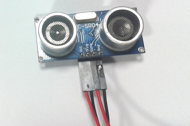
So, the Trig pin of HC-SR04 is made high for at least 10 us. A sonic beam is transmitted with 8 pulses of 40KHz each.
The signal then hits the surface and return back and captured by the receiver Echo pin of HC-SR04. The Echo pin had already made high at the time sending high.

The time taken by beam to return back is saved in variable and converted to distance using appropriate calculations like below
Distance= (Time x Speed of Sound in Air (343 m/s))/2
We used ultrasonic sensor in many projects, to learn more about Ultrasonic sensor, check other projects related to Ultrasonic sensor.
The components for this obstacle avoiding robot can be found easily. In order to make chassis, any toy chassis can be used or can be custom made.
Components Required
- Arduino NANO or Uno (any version)
- HC-SR04 Ultrasonic Sensor
- LM298N Motor Driver Module
- 5V DC Motors
- Battery
- Wheels
- Chassis
- Jumper Wires
Circuit Diagram


Programming Arduino for Obstacle Avoiding Robot
Complete program with a demonstration video is given at the end of this project. The program will include setting up HC-SR04 module and outputting the signals to Motor Pins to move motor direction accordingly. No libraries will be used in this project.
First define trig and echo pin of HC-SR04 in the program. In this project the trig pin is connected to GPIO9 and echo pin is connected to GPIO10 of Arduino NANO.
int trigPin = 9;      // trig pin of HC-SR04
int echoPin = 10;     // Echo pin of HC-SR04
Define pins for input of LM298N Motor Driver Module. The LM298N has 4 data input pins used to control the direction of motor connected to it.
int revleft4 = 4;       //REVerse motion of Left motor
int fwdleft5 = 5;       //ForWarD motion of Left motor
int revright6 = 6;      //REVerse motion of Right motor
int fwdright7 = 7;      //ForWarD motion of Right motor
LM298N Motor Driver Module

In setup() function, define the data direction of utilised GPIO pins. The four Motor pins and Trig pin is set as OUTPUT and Echo Pin is set as Input.
pinMode(revleft4, OUTPUT);      // set Motor pins as output
pinMode(fwdleft5, OUTPUT);
pinMode(revright6, OUTPUT);
pinMode(fwdright7, OUTPUT);
pinMode(trigPin, OUTPUT);         // set trig pin as output
pinMode(echoPin, INPUT);          //set echo pin as input to capture reflected waves
In loop() function, get the distance from HC-SR04 and based on the distance move the motor direction. The distance will show the object distance coming in front of the robot. The Distance is taken by bursting a beam of ultrasonic up to 10 us and receiving it after 10us. To learn more about measuring distance using Ultrasonic sensor and Arduino, follow the link.int trigPin = 9; // trig pin of HC-SR04
int echoPin = 10; // Echo pin of HC-SR04
int revleft4 = 4; //REVerse motion of Left motor
int fwdleft5 = 5; //ForWarD motion of Left motor
int revright6 = 6; //REVerse motion of Right motor
int fwdright7 = 7; //ForWarD motion of Right motor
int fwdleft5 = 5; //ForWarD motion of Left motor
int revright6 = 6; //REVerse motion of Right motor
int fwdright7 = 7; //ForWarD motion of Right motor
long duration, distance;
void setup() {
delay(random(500,2000)); // delay for random time
Serial.begin(9600);
pinMode(revleft4, OUTPUT); // set Motor pins as output
pinMode(fwdleft5, OUTPUT);
pinMode(revright6, OUTPUT);
pinMode(fwdright7, OUTPUT);
pinMode(trigPin, OUTPUT); // set trig pin as output
pinMode(echoPin, INPUT); //set echo pin as input to capture reflected waves
}
void loop() {
digitalWrite(trigPin, LOW);
delayMicroseconds(2);
digitalWrite(trigPin, HIGH); // send waves for 10 us
delayMicroseconds(10);
duration = pulseIn(echoPin, HIGH); // receive reflected waves
distance = duration / 58.2; // convert to distance
delay(10);
// If you dont get proper movements of your robot then alter the pin numbers
if (distance > 19)
{
digitalWrite(fwdright7, HIGH); // move forward
digitalWrite(revright6, LOW);
digitalWrite(fwdleft5, HIGH);
digitalWrite(revleft4, LOW);
}
if (distance < 18)
{
digitalWrite(fwdright7, LOW); //Stop
digitalWrite(revright6, LOW);
digitalWrite(fwdleft5, LOW);
digitalWrite(revleft4, LOW);
delay(500);
digitalWrite(fwdright7, LOW); //movebackword
digitalWrite(revright6, HIGH);
digitalWrite(fwdleft5, LOW);
digitalWrite(revleft4, HIGH);
delay(500);
digitalWrite(fwdright7, LOW); //Stop
digitalWrite(revright6, LOW);
digitalWrite(fwdleft5, LOW);
digitalWrite(revleft4, LOW);
delay(100);
digitalWrite(fwdright7, HIGH);
digitalWrite(revright6, LOW);
digitalWrite(revleft4, LOW);
digitalWrite(fwdleft5, LOW);
delay(500);
}
}
Comments
Post a Comment